Friday, November 22, 2013

This is an updated assembly of the launcher. A base plate has been added as well as legs to support the base. The bearings, that hold the wheels centered from the top,will be screwed down to the base plate.


All of the parts have been uploaded as JPEGs onto the google drive for viewing. 

Thursday, November 21, 2013

11/21/2013
On 11/21/2013 we met as a group in lab. Today we further researched the issue of an h bridge, and detrermined that we would order the one from the sparkfun website shown 
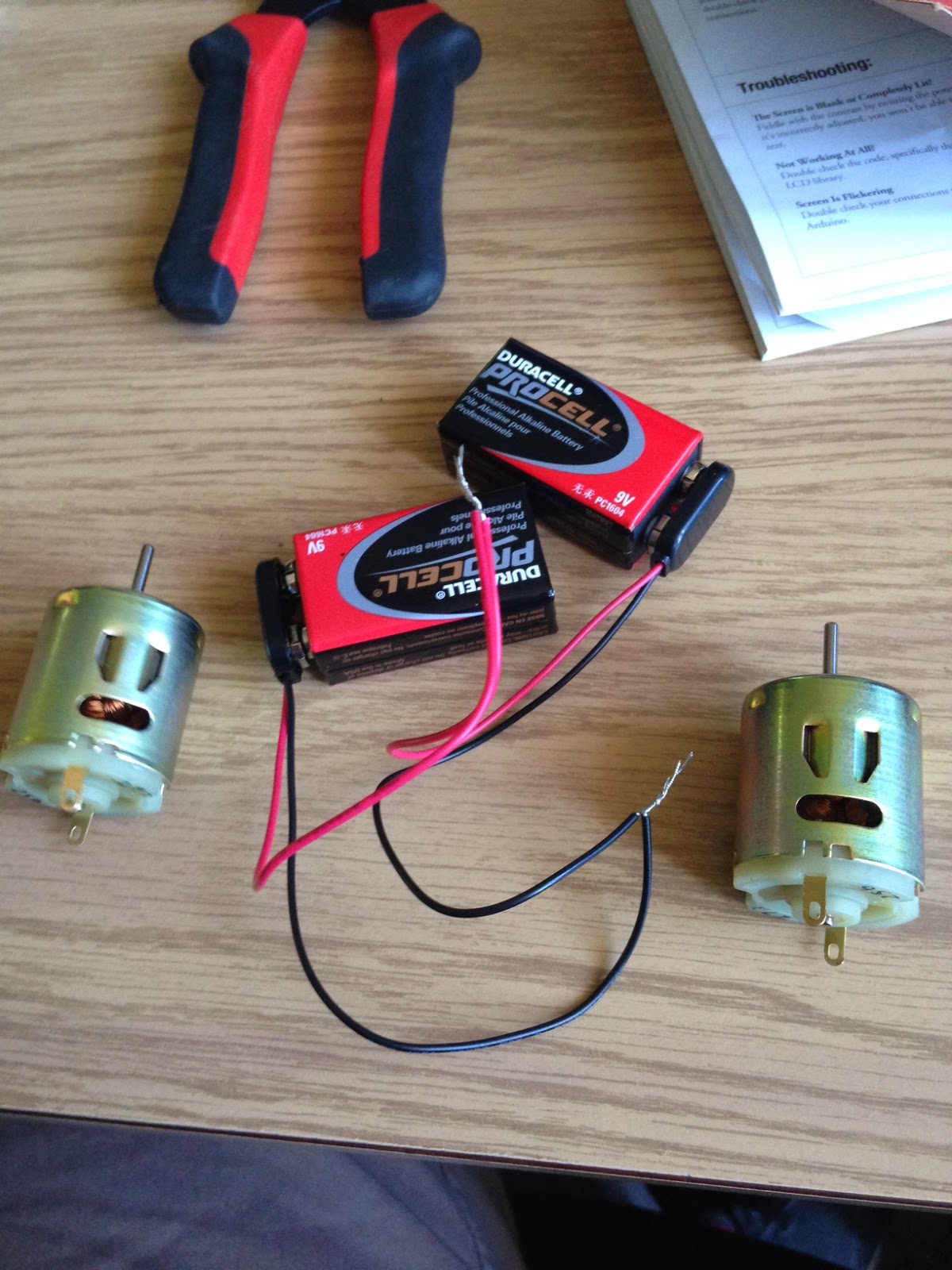
here. We tested the new motors and the various speeds using the serial monitor. We shortened and organized the wires on the existing circuit that contains the push botton and the servo that will be used as an arm to release the ping pong balls. We are working on creating a program that will allow one ball to be released when the button is pushed, and all of the balls to be released at once when the button is held down. Shown below is a picutre of the motor test circuit, and the circuit that will be used to control the servo.


 Also today, all of the parts that are supposed to be 3d printed are created on solid works. Today, measurements were taken in order to make the design more precise. A new idea today was to have the motors below the bottom of the base of the assembly and then build legs that the assembly will sit on when it is placed on a table to run. The parts built used .02 inches of tolerance between the plastic pieces that will be moving. A final assembly of these parts will be shown above.


11/20/2013

On 11/20/2013, we began to acquire the parts in order to start constructing some of the ball launcher. These parts included two 9-18v motors, wire, solder, connectors, and batteries. We began to finalize sketches and determine exactly what parts will be 3D printed. The part that we had difficulty finding was an H-Bridge to control the two motors. Radioshack only had a motor shield that would have worked, however it was rather expensive and did more than we needed it to. At this point, we will either build our own H-Bridge, or continue to try to find a cheaper IC version of the H-Bridge. We decided today that the arm attached to the servos will be located inside of the barrel where the ping pong balls are, and also that there is going to be the least amount of space possible between the barrel and the motors to launch the ball. This will minimize the chance of a ball getting stuck and will also reduce the footprint of the device.

Below is a piture of the two 9-18v motors that we will be using.

Monday, November 18, 2013

Sketches

So here are a couple sketches of the general design of our launcher.  From here the parts are going to be built, designed, printed, and the corresponding programming will be created.


Sunday, November 17, 2013

Solid Works Motion Study

This link is to the Google Drive folder. Click on the video folder and in that open the wheel and bearing assembly. This will show a video of the assembly in motion.


https://drive.google.com/folderview?id=0BzW08nfMMiccbmd6NjhzbHJlNnM&usp=sharing


Solid Works Assembly

This Picture is of the ping pong ball launcher.  The wheels will rotate in opposite directions to launch the ping pong ball outward and will be driven by DC motors on the bottom of the wheel.  A video of the motion study will be posted soon.


Thursday, November 7, 2013

Google Drive

This is the link to our Google Drive. Here we will be posting our solid works parts and any other large files worth viewing.

https://drive.google.com/folderview?id=0BzW08nfMMiccbmd6NjhzbHJlNnM&usp=sharing

Welcome!

Welcome to the Death By Donkey Pong blog.  Here we will be designing a Donkey Kong themed ping pong ball laucher. We will be updateing this blog on our progress throughout this project and hopefully by the end we will be successfull. Hope you like it and wish us luck!