Designing, printing, programming, and building a Death By Donkey Pong ping pong ball launcher was not an easy feat. For that reason, we had a team to do this so we could effectively and efficiently construct our project. We divided up the tasks and completed them as follows:
Kyle Fitzpatrick-
Throughout the project I took care of the programming and wiring. When the project began, we immediately knew that a servo motor was going to control the the rate of ping pong balls fired. So, that was the first part I began working on in the lab time provided. For fully automatic fire and semi-automatic fire, we needed at the press of a push-button for the servo to let a ball through then automatically return to its original position. Before it returns, there needed to be another analog read function to tell if the button was held down. In this case, the launcher would become fully automatic. This was difficult to do but after hours of tinkering, I got it working. By this point, the h-bridge to run our motors was only a few days away. I therefore began my research on how to work and program the h-bridge to do what we wanted. I then made a theoretical program that i would test when the part came in. This program included a potentiometer that controlled the speed of the motors and therefore the distance of the balls as well as a switch that turned the enable pins high or low (turn the motors on and off) regardless of the potentiometer value. At this point i also began wiring the board. I attached the servo and the corresponding wires that would be where the h-bridge was. When we received the h-bridge, I simply plugged it in to the programmed spots then wired it to the motors. It worked with 2 9-volt batteries but not as fast as we hoped. The motors were rated for up to 18 volts so Nick and I picked up more 9-volts and I wired 4 of them together in series to get the maximum voltage. To neaten everything up, I used connecting wire to remove the unnecessarily long arduino wires and to make longer wires for the motors. Nothing ever works at first, so the programming and wiring needed tweaking as the hardware and setup of the project developed. One of the main problems was with the h-bridge. It kept getting extremely hot to a point that we were worried it would break the bridge or my board. So Nick and I purchased a heat sink, heat compound, and a small fan to keep it cool, This was installed by by both Nick and I. Other parts i helped with on the project was building the major components with Nick whenever he needed a second set of hands or another opinion.
Nicholas Paolino- My contribution to the project is as follows: I took on the roles of sketching and construction of the ping pong ball launcher, as seen on the blog, throughout the first few group meetings I developed sketches of what I thought the launcher should look like. I sketched out the base, the wheels, and the motor mounts. These parts were all laser cut or 3D printed. Construction began when Kyle and I made a trip to my house to work in my garage and acquire parts. I began construction by inserting the legs into the base, and then super gluing them just to ensure stability. Next, I drilled holes in the pilot holes and placed the wheels into the motor mounts, and then attached the motor mounts to the base with nuts and bolts. Kyle and I went to Lowes and consulted with a worker about how to attach the motors to the motor mounts, and he sold me "L" brackets, hardware, and glue to do the job. I proceeded to follow his recommendation and it worked, however the motor shaft often came loose from the wheel due to vibration, so I had to drill a bigger hole in it and add super glue to ensure a tight fit. The next step was to design and build a tube that would hold the balls and then release them in front of the motors. I went to home depot and bought a pvc elbow, couplers, hose clamps, and a holder for a fluorescent light bulb. I brought a ping pong ball in and made a prototype while I was in the store. I constructed the pipe out of these materials by attaching the couplers to the elbow and securing them with hose clamps. Next, I inserted the fluorescent light holder into the top coupler and secured it with a hose clamp. I then began to measure and drill pilot holes in the base where I would be attaching the tube. I constructed brackets out of parts from an erector set to attach the tube. I super glued the brackets to the tube, and then attached the brackets to the base with nuts and bolts. Then, the servo motor was attached to the tube with super glue. I performed many other small construction tweaks during, and after testing. After the construction was completed, and after Kyle finished programming, I soldered all of the wire connections where he told me to, since I have previous soldering experience. The final bill of all of the necessary materials was $120. After I finally finished the construction after numerous hours of designing and building, I was satisfied with the results as the finished product looks and functions like I had envisioned.
Jeffrey Dimanna- I designed and created all of the parts all in SolidWorks. These were printed and laser cut. I designed the wheels to be as light as possible while still being strong enough to withstand the forces that would be put on them. I designed the brackets to be hollow only to conserve material. There were a few issues with the size of the base. I thought i had the full 12 inches to build the base so i made a 12x12 square but learned later that it had to be smaller than that, so dimensions had to be adjusted. This was made more difficult since i had not dimensioned from the center of the base but rather the edges so new dimensions had to be made otherwise the parts would not mach up. The diameter of the shaft of the wheel, and the hole in the base were difficult to know just how much space would be needed so that it would spin free but also not wobble. If I was to remake it again I would have made a slightly tighter fit than this time around. Also, the original plan was to mount the motors on the bottom which would provide more stabilization for the wheel, but the motors ended up being mounted on the top. If I had known that they couldn't be mounted on the bottom, two more brackets would have been made for the bottom. For stability, the legs attached to the base were flared out. There were definitely things that could be improved upon in the future in every aspect of the project but overall this was a successful and fun project to work on. I am in the process of uploading a video of the working launcher to the Google drive but this is proving difficult since the file type does not match up. Hopefully i can get this squared away so it will be available for viewing.
Saturday, December 14, 2013
Wednesday, December 11, 2013
12/11/13
Tonight, we created a tube out of PVC pipe, and a florescent light bulb holder that was exactly the right size to hold the ping pong balls. Then, this pipe was attached to the base and a servo motor was attached to the pipe which held the balls in place. After attaching the pipe and the arduino board, the project was almost completely built. All that is left is to sand the wheels to reduce friction, and add rubber bands to the wheels. Below are pictures of the almost complete project.


12/5/13
Construction of the project began on December 5th, which is when the 3D printed parts and the laser cut parts were ready. On this day, we attached the legs to the base which were made out of acrylic and were laser cut. Then, we attached the wheels and the motor mounts which were 3D printed. In the design of the parts, pilot holes were laser cut in order to make pre drilling the holes in the acrylic easier. The next step was to create and mount a tube that would hold the ping pong balls before they were released.


Sunday, December 1, 2013
Over break, more wiring and programming for our board was done. The h-bridge is not yet connected and the motors are still at school so the testing for the motors couldn't be done unfortunately. Since the video, more progress was made on the automatic-fire debounce program which will hopefully be completed soon.
This video shows what the board looks like so far.
This is the coding so for for both the servo and the motors. It is still not fully tested and not completed so don't judge.
This video shows what the board looks like so far.
This is the coding so for for both the servo and the motors. It is still not fully tested and not completed so don't judge.
Friday, November 22, 2013

Thursday, November 21, 2013
11/21/2013
On 11/21/2013 we met as a group in lab. Today we further researched the issue of an h bridge, and detrermined that we would order the one from the sparkfun website shown here. We tested the new motors and the various speeds using the serial monitor. We shortened and organized the wires on the existing circuit that contains the push botton and the servo that will be used as an arm to release the ping pong balls. We are working on creating a program that will allow one ball to be released when the button is pushed, and all of the balls to be released at once when the button is held down. Shown below is a picutre of the motor test circuit, and the circuit that will be used to control the servo.


Also today, all of the parts that are supposed to be 3d printed are created on solid works. Today, measurements were taken in order to make the design more precise. A new idea today was to have the motors below the bottom of the base of the assembly and then build legs that the assembly will sit on when it is placed on a table to run. The parts built used .02 inches of tolerance between the plastic pieces that will be moving. A final assembly of these parts will be shown above.
On 11/21/2013 we met as a group in lab. Today we further researched the issue of an h bridge, and detrermined that we would order the one from the sparkfun website shown here. We tested the new motors and the various speeds using the serial monitor. We shortened and organized the wires on the existing circuit that contains the push botton and the servo that will be used as an arm to release the ping pong balls. We are working on creating a program that will allow one ball to be released when the button is pushed, and all of the balls to be released at once when the button is held down. Shown below is a picutre of the motor test circuit, and the circuit that will be used to control the servo.

Also today, all of the parts that are supposed to be 3d printed are created on solid works. Today, measurements were taken in order to make the design more precise. A new idea today was to have the motors below the bottom of the base of the assembly and then build legs that the assembly will sit on when it is placed on a table to run. The parts built used .02 inches of tolerance between the plastic pieces that will be moving. A final assembly of these parts will be shown above.
11/20/2013
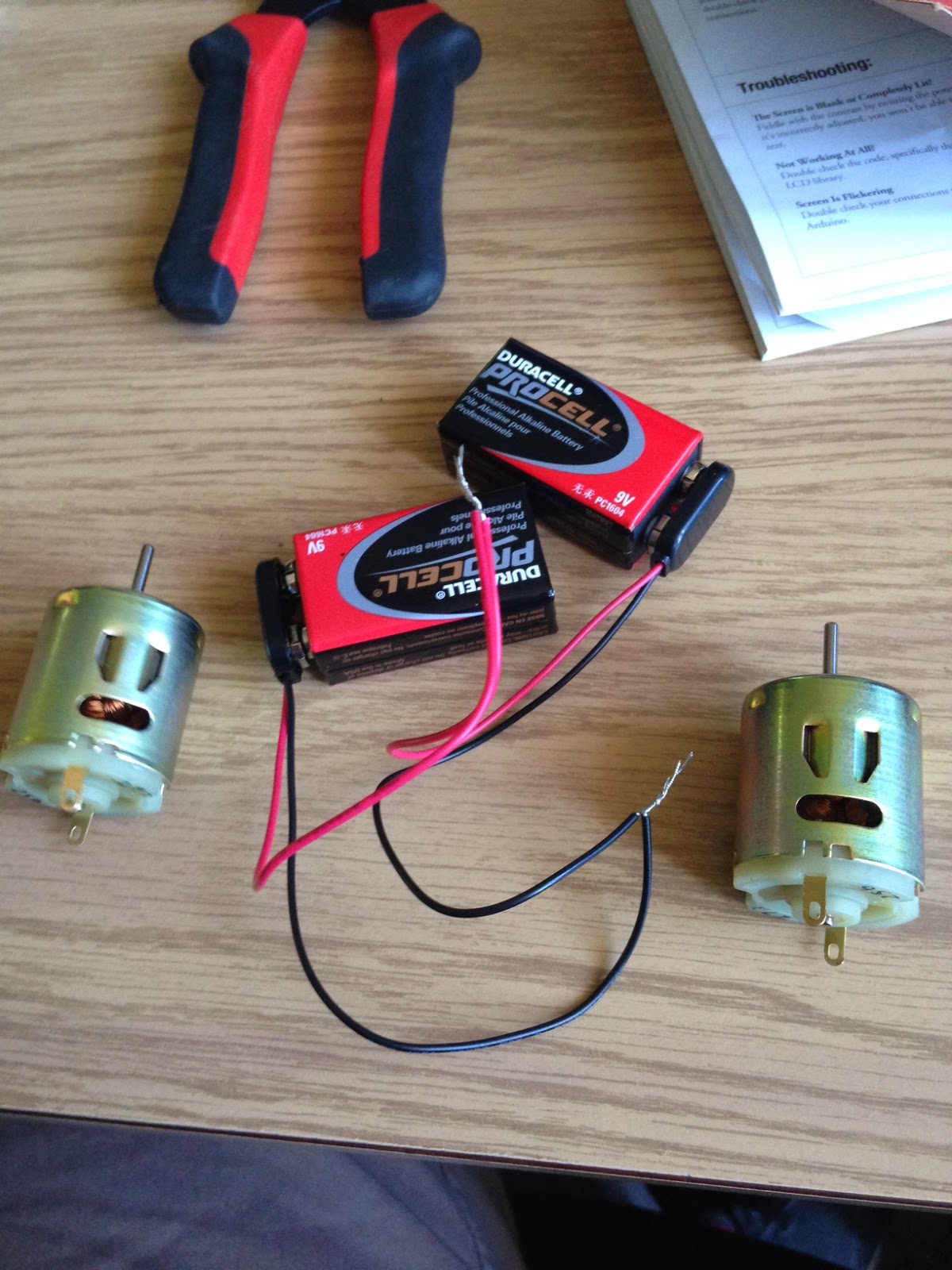
On 11/20/2013, we began to acquire the parts in order to start constructing some of the ball launcher. These parts included two 9-18v motors, wire, solder, connectors, and batteries. We began to finalize sketches and determine exactly what parts will be 3D printed. The part that we had difficulty finding was an H-Bridge to control the two motors. Radioshack only had a motor shield that would have worked, however it was rather expensive and did more than we needed it to. At this point, we will either build our own H-Bridge, or continue to try to find a cheaper IC version of the H-Bridge. We decided today that the arm attached to the servos will be located inside of the barrel where the ping pong balls are, and also that there is going to be the least amount of space possible between the barrel and the motors to launch the ball. This will minimize the chance of a ball getting stuck and will also reduce the footprint of the device.
Below is a piture of the two 9-18v motors that we will be using.

Below is a piture of the two 9-18v motors that we will be using.
Subscribe to:
Comments (Atom)